1 Introduction
Falloff maps are an extremely powerful tool for an artist to have when creating procedural shaders. They are essential when trying to create any realistic shader that is reflective or has color changing properties like chrome, metals, and pearlescent paint. In order to use Falloff maps effectively it is important to understand how the map works. This document will help explain Falloff map parameters and demonstrate usage.
2 Setting Colors
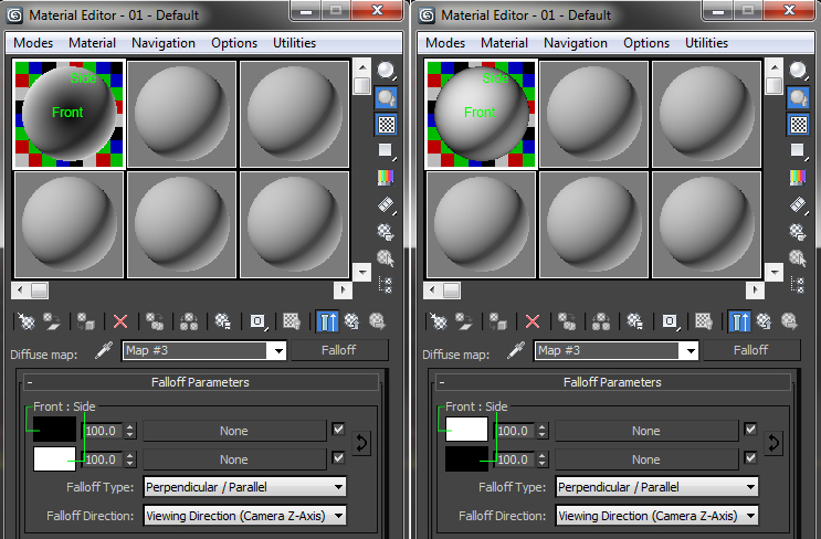
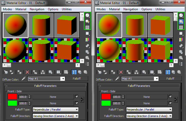
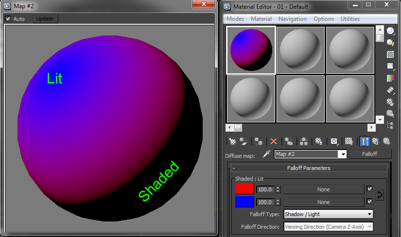
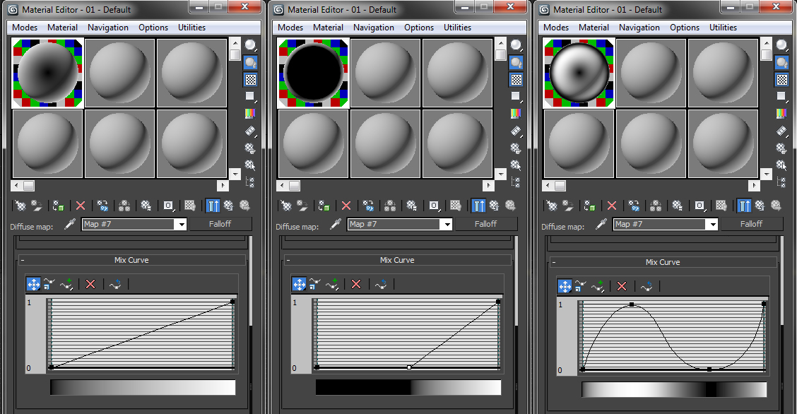
The first editable parameter is map colors. Both of these colors will be actively blended using the Falloff type selected for the map. Texture maps or other maps can be used in place of colors as well. For the examples the Falloff is placed in the diffuse slot. The default colors are black (0,0,0) and white (255, 255, 255).
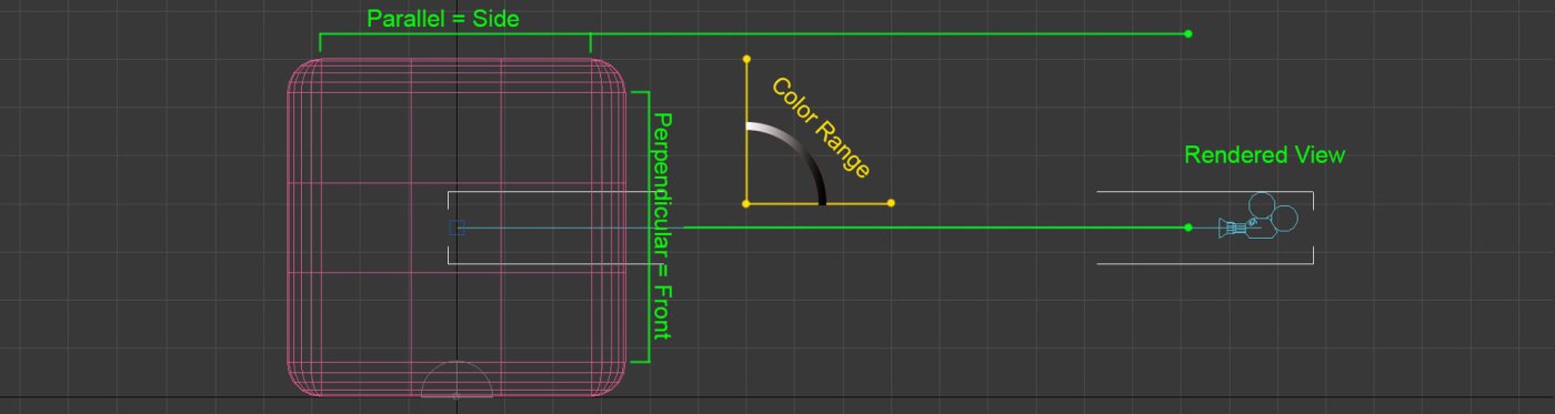
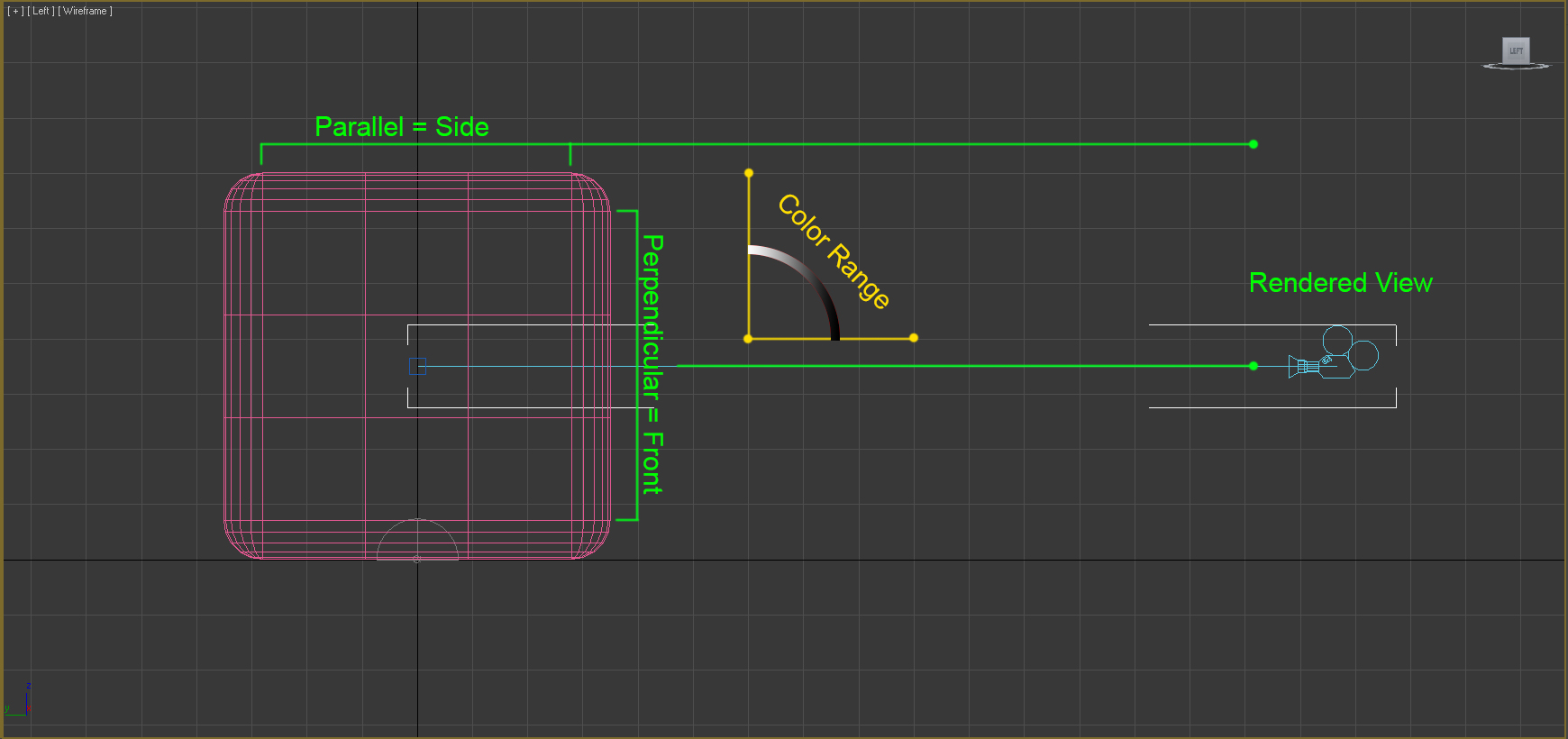
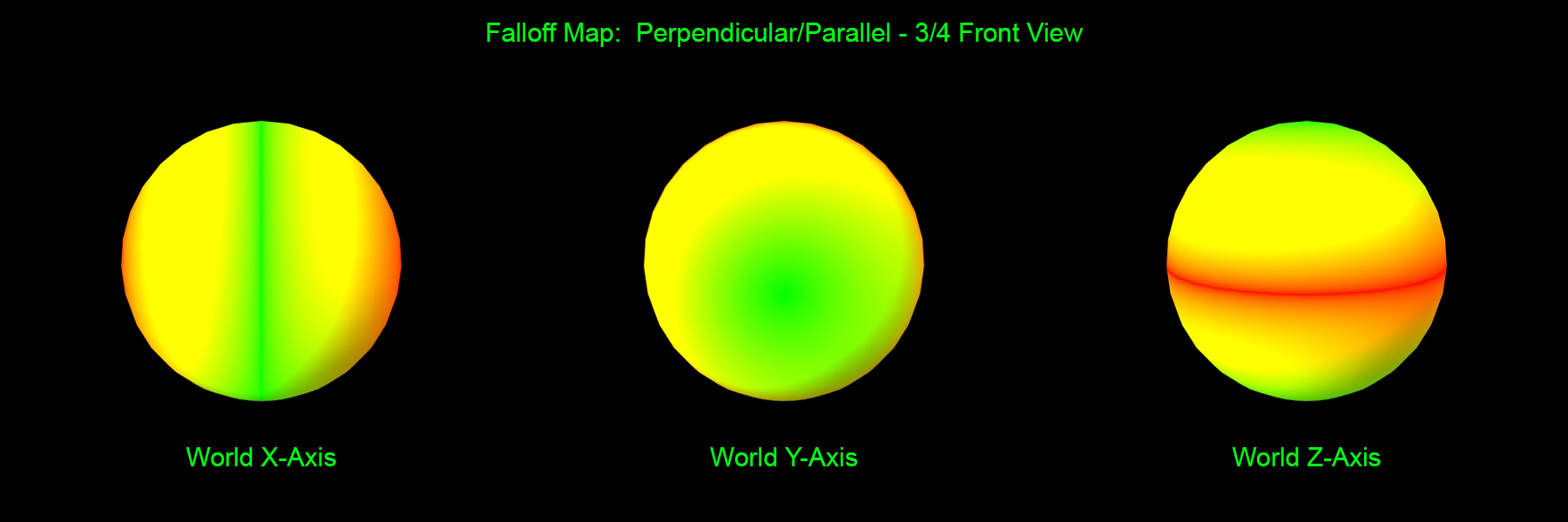
The name of the group is at the top of this rollout. This name changes depending on the falloff type selected, which is covered below. In all cases, the name on the left refers to the top color parameter, and the name on the right to the bottom color parameter. In the case of Perpendicular/Parallel black is the front color and white is the side color. Colors can easily be inverted by clicking the arrow button on the right side to swap colors. Viewing the material node it is easy to see how the colors react for the type of falloff you are using.
3 Choosing the Right Falloff Type
There are five different types of Falloffs that can be used. It is very important to know how each one reacts so you can choose the correct one for your intended purpose. For these examples all settings on the Falloff map have been left at default except for changing the type.
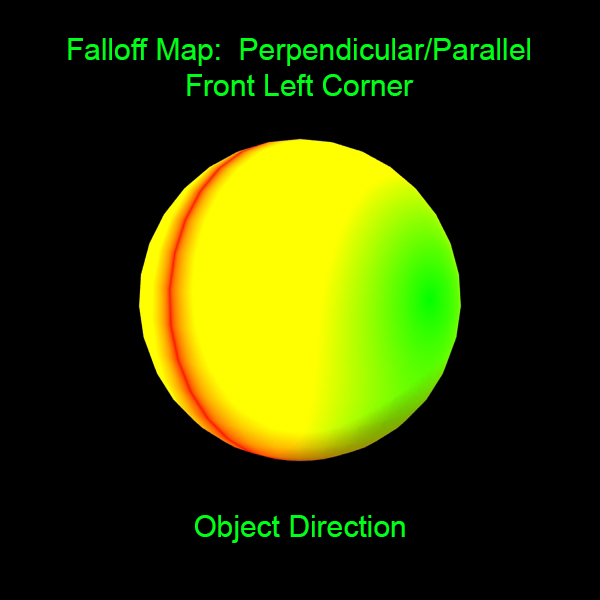
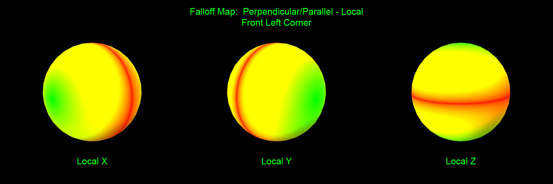
3.1 Perpendicular/Parallel
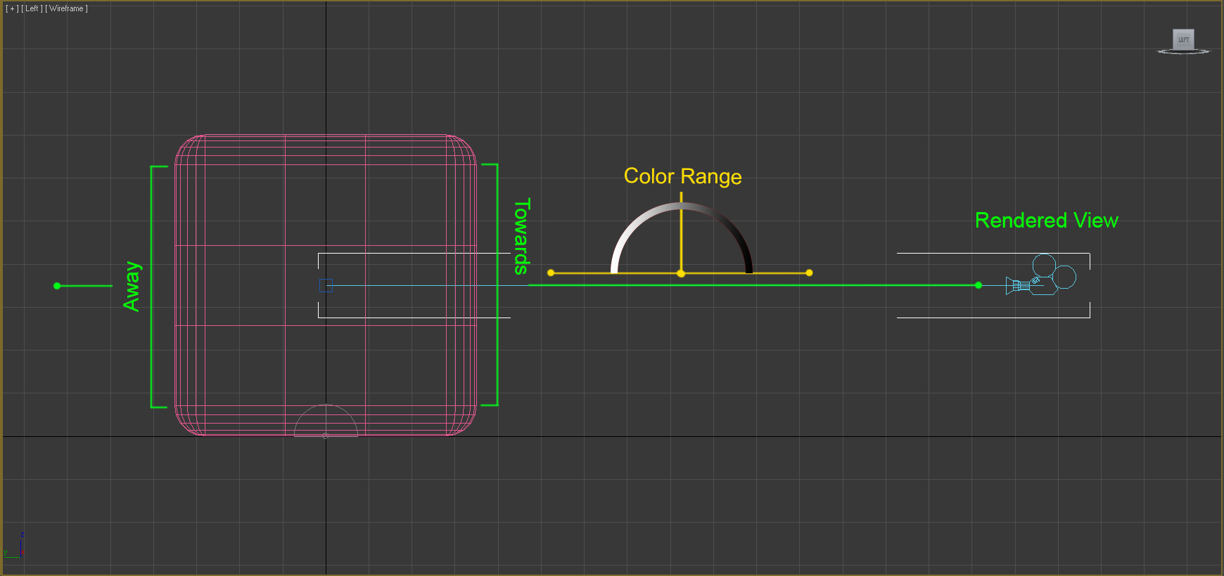
3.2 Towards/Away
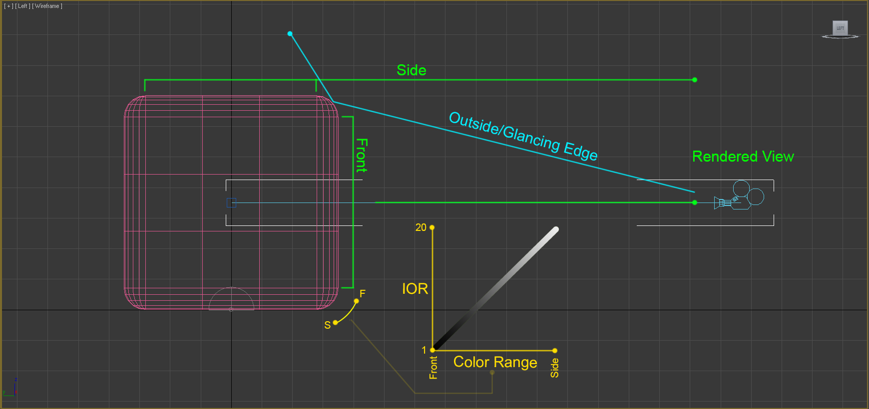
3.3 Fresnel
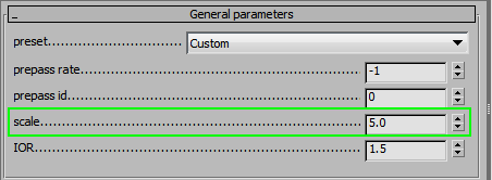
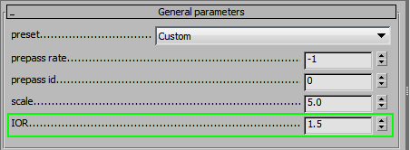
This type of fall off is primarily use in the Reflection slot. At default values it results in dim reflections on surfaces facing the view, with much brighter reflections on angled faces, creating highlights like those on the sides of a glass. VrayMTL has a Fresnel reflections box, when checked on, calculates the Reflection as a Fresnel type Falloff map being appied. The Front color defaults to black. If you want a different Front color you will need to apply a actual Falloff map to the Reflection slot. The Reflect color you set becomes the Side color. The Fresnel IOR value by default is locked at 1.6 but can be unlocked to be adjusted.
3.5 Distance Blend
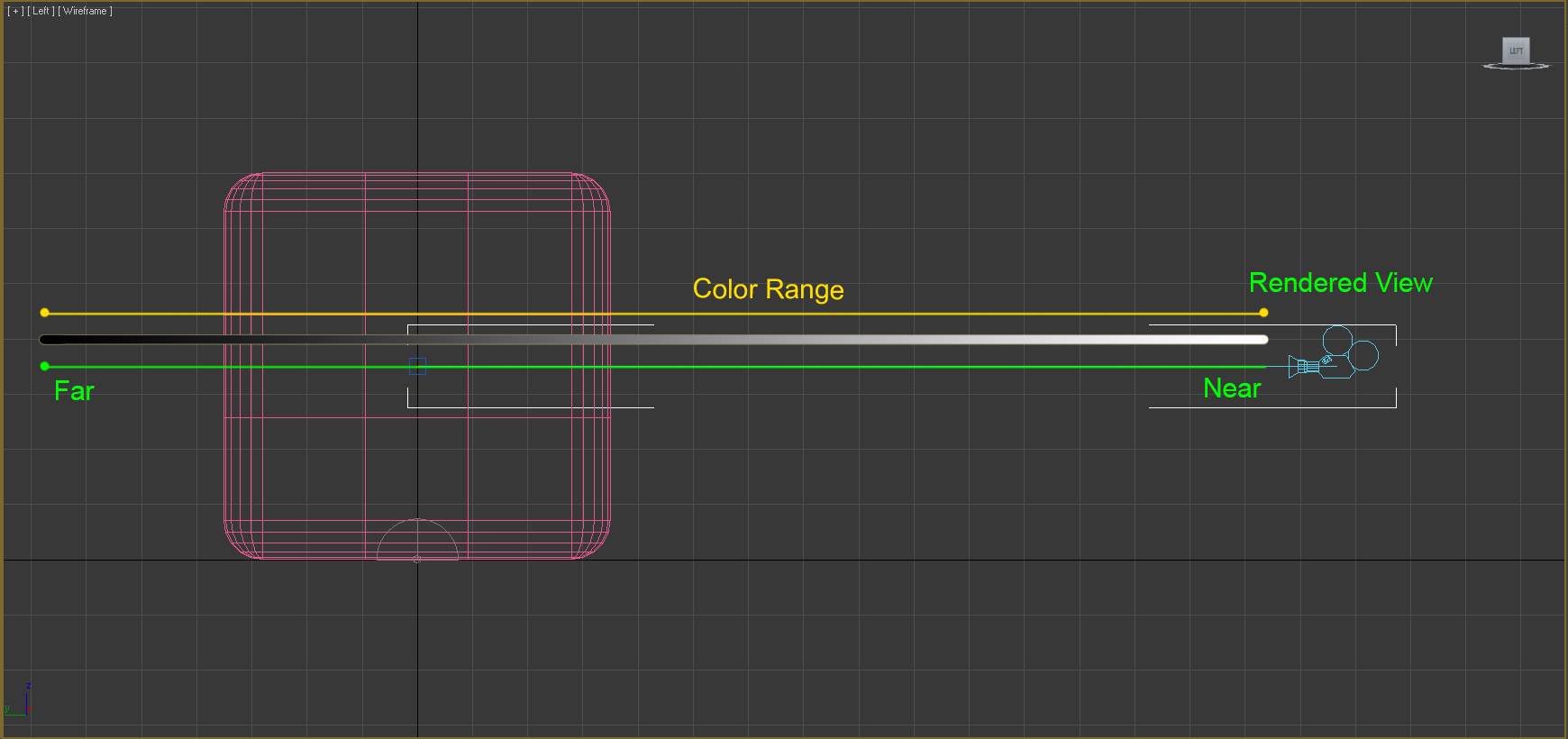
4 QualityFalloff Direction
There are five direction options to choose from in order to achieve the desired outcome. The default is usually correct for most material types, but they may be situations that you would want to change the falloff direction.
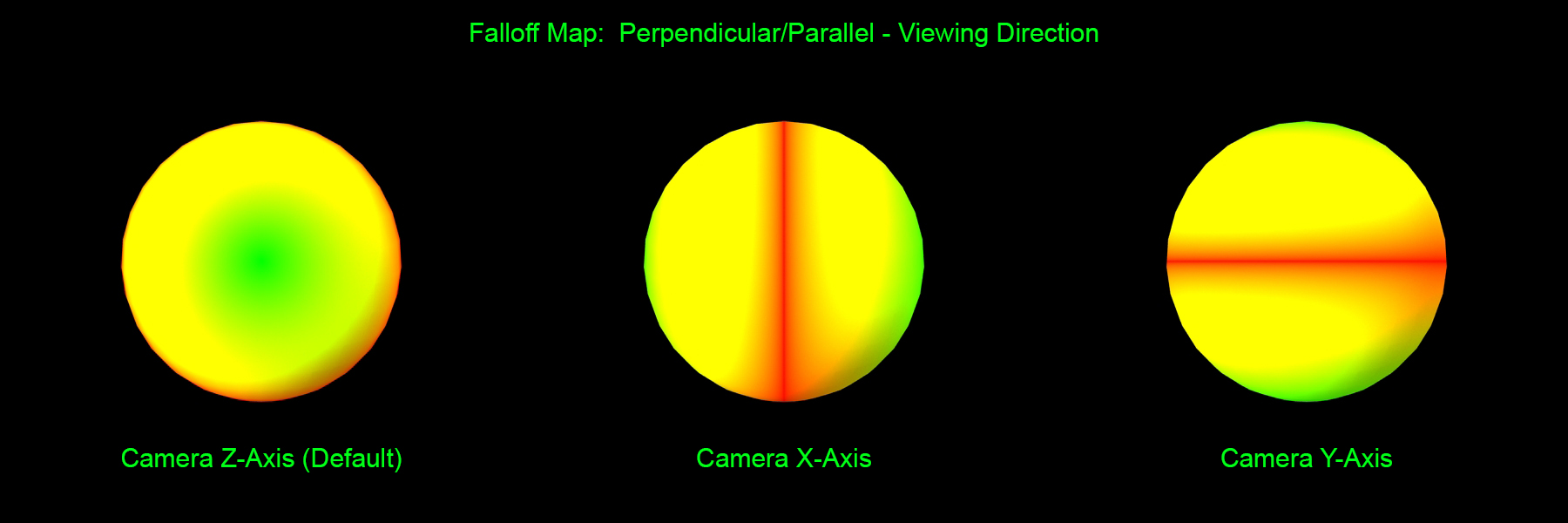
4.2 Camera X/Y Axis
Similar to Viewing Direction except using Camera X-Axis changes the color range from left to right of the rendered view. Camera Y-Axis changes to color range from top to bottom of the rendered view . (See above for example)
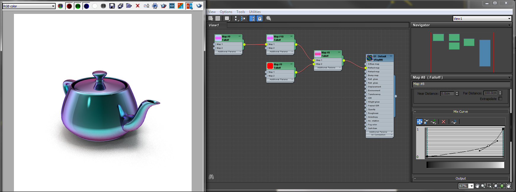
5 Mix Curve
As you manipulate the curve the gradient bar underneath the curve indicates how it affects the color range. This is more reliable to view than looking at the node as your falloff may not be in the diffuse slot as it is in the examples.
Usually no alteration is needed for the mix curve for common material types. However, it can come in handy when making more difficult materials like color shifting surfaces such as iridescence, metallics, and pearlescents.