Please note that this page will soon be deprecated.
We highly recommend switching to the NEW StemCell v2 spec.
Click here for more info.
The StemCell v1 3D modeling specification is built on best practices that allow 3D models to be easily converted for multiple applications and uses. All models submitted for StemCell on TurboSquid must meet the criteria below. However, specification points that contain the RT suffix are intended for artists creating StemCell content for real-time gaming exports. Not meeting the RT criteria will disqualify a model from being converted to Unity or Unreal but can still be converted to other DCC applications.
1. Geometry
1.1 No rigged models
1.2 No animation
1.3 No isolated vertices
1.4 No coincident vertices
1.5 No coincident/coplanar faces
1.6 Minimal Visible Faceting – The silhouette of the model must have minimal noticeable faceting without subdivision modifiers. Most common issue for this is on round objects or sections where they intersect another surface or the background. There must be sufficient geometry for the intended silhouette of the model without drastically increasing mesh density. Relatively smaller rounded details will require less geometry to appear round when viewing the whole model. Adjust accordingly.
Example
Round legs on a table chair may only need 8 to 10 sides. Faceting would be minimally visible where the legs meet the ground or intersect with another section of the model. The thicker or larger the rounded legs, the more sides it will need to appear proportionally smooth curved.1.7 No coincident edges (Unwelded Seams) – Any two edges on an object that meet or overlap in the same position must be welded.
1.8 No inverted face normals – No backfacing or inverted face normals. All normals should be pointing out toward the correct direction for rendering without errors.
1.9 No empty objects – All objects must be geometry or splines. Any empty objects need to be removed from the scene.
1.10 No use of smoothing groups or crease values to create hard edges – Objects should render correctly using a single smoothing group without visible faceting.
1.11 Intelligently Grouped or Combined Objects – Complex models should be intelligently combined into groups of objects. Objects must be broken up by shared material or logically by modular sections for editability. See Scene Organization and Best Practices for more detailed information.
Example
A car model can be organized with the whole body as a single object. Glass objects, such as windows, should also be combined into a separate object. The wheel, tire, and their small details combined into one object for each position on the vehicle.1.12 Model Master Group – Entire model should be contained within a master group named the same as the model. This helps keep scenes organized when converted and merging files into new scenes.
1.13 Model on Single Non-Default Layer – Entire model should be contained within a single non-default layer named the same as the model scene. This helps keep scenes organized when converted and merging files into new scenes.
1RT. Geometry
1.1 RT Sealed Geometry – Geometry must be completely sealed so that there are no openings where backfaces would be visible. This includes geometry visible through transparent objects or materials.
2. Real-World Scale
2.1 Real-world scale within 1% – Model must be in centimeter units at real-world scale. If the model does not have an exact real-world counterpart (such as a human character or an unbranded car), the model must use the size/scale of comparable objects in real life.
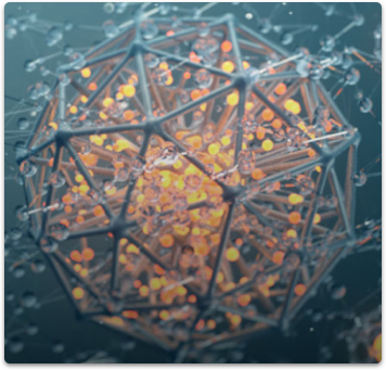
2.2 Exception for exceedingly large/small models – Models of objects that have a real-world scale that require magnification or distance to see, such as amoebas and solar systems, are excepted from having real-world scale.
3. Position and Orientation
3.1 Center Origin – The model should be centered over the scene origin, and the lowest point of the object sitting on the ground plane. The object should never be lower than the ground plane.
3.2 Orthographic Orientation – The model should be oriented to the orthographic positions as it would be considered in the real world. In other words, the model can’t be lying on its side, upside-down, backwards, or turned sideways when the file is opened.
Example
A car’s front end must be facing the Front View and its roof facing the Top View.4. Transforms
4.1 Model transforms, such as rotation and scale, must be reset or frozen – Transforms must be reset so object reads at 100% scale size, rotation, and position.
5. UVs
5.1 UV Mapping – All objects must have UVW mapping or be UV unwrapped. StemCell relies on texture maps so that models can be converted to multiple renderer and app outputs. Applying texture maps to a model with no UV mapping can render as stretched or distorted.
5RT. UVs
5.1 RT UVs intelligently atlased – The final packed UVs should have minimal negative/wasted texture space. The model can use more than one texture map. There can be more than one set of unwrapped UVs per model. It is generally a good practice for different material types to be on different UV sets to maximize texel density.
Example
A box of crayons can logically have 2 to 3 UV sets. One UV map for the crayon box, and another UV map for the actual crayons. However, if the crayon labels have separate geometry then the labels would have their own separate UV map.6. Textures and Materials
6.1 All objects must have a material applied
6.2 Texture Maps are a standard power of two square resolution (512×512,1024×1024,2048×2048, 4096×4096, etc.) – Texture maps size should be determined by amount of detail needed. Being conscious of the texture size helps optimize render times and file transfers for submission. If a smaller resolution can be used with no noticeable difference on the render, do so. Try to keep map usage and size as efficient as possible. Texture set needs to be the same size across all the maps for a given material. (Ex. 512×512,1024×1024, 2048×2048, 4096×4096, etc.)
6.3 All texture maps must be saved as 8-bit lossless or uncompressed PNG or TGA.
6.4 No procedural materials – Any edits done to the material during creation must be applied or baked into the texture maps. It is preferable that texture map manipulation be done to the texture maps directly through Photoshop or other digital imaging software.
6.5 Logically Separate Materials – Materials must be logically separated by UV map and/or material type. Materials that require drastically different settings from other materials that share same UV map must be separated into a different material. This is necessary for generating accurate renderings of the intended material.
Example
A chrome car rim and a rubber tire can be on the same UV map but should be separate objects. Chrome and rubber are drastically different materials. There should be a rubber material applied to the tire and a chrome material applied to the rim. This way the chrome can be set with the correct higher IOR value and the rubber can be at a lower IOR value on its own material. The two materials share the same textures maps still.6.6 Materials and texture maps set up in TS calibrated environment
6.7 Textures must be in a Specular/Glossiness workflow for production renderers
6.8 All core Specular/Glossiness texture maps present – Diffuse, Specular, Glossiness, and Normal maps are all required texture maps. See table below for correct naming.
6.8.1 Naming Conventions – Texture maps must be named with the same name as the material they are applied to followed by the correct suffix. All texture file names must be suffixed correctly as listed below. There must be no text after the suffixes. Example: GlossyPlastic_Diffuse.PNG.
Some additional maps may be required when additional effects are present (Self Illumination, Opacity, etc.). Follow suffix naming conventions listed below.
6.8.2 Correct Color Space – Each texture map must be in the correct color space as defined in the table below.
| Specular Workflow – Color Space Profile specified | Naming Convention (Suffixes) |
| Diffuse (Specular/Glossiness) – sRGB | _Diffuse |
| Reflect (Specular/Glossiness) – sRGB | _Specular |
| Glossiness (Specular/Glossiness) – Linear | _Glossiness |
| Refraction (Common) – Linear | _Refraction |
| Shared/Common Maps – Color Space Profiles specified | Naming Convention (Suffixes) |
| Normal (Common) – Linear | _Normal |
| Self Illumination (Common) – sRGB | _Emissive |
| Opacity (Common) – sRGB | _Opacity |
Note:
When using Substance Painter to produce texture maps for the Specular/Glossiness workflow, the maps exported for Specular will need value adjustments to look correct in production renderers.6RT. Textures and Materials
6.1 RT Textures must be in a PBR Metallic Workflow for real time renderers.
6.2 RT All core PBR Metallic texture maps present – BaseColor, Metallic, Roughness, Normal, and Ambient Occlusion maps are all required texture maps. See table below for correct naming.
6.2.1 RT Texture maps must be named with the same name as the material they are applied to followed by the correct suffix. All texture file names must be suffixed correctly as listed below. There must be no text after the suffixes. Example: ChippedPaint_BaseColor.PNG.
Some additional maps may be required when additional effects are present (Self Illumination, Opacity, etc.). Follow suffix naming conventions listed below.
6.2.2 RT Correct Color Space – Each texture map must be in the correct color space as defined in the table below.
| Metallic Workflow – Color Space Profiles specified | Naming Convention (Suffixes) |
| Albedo (PBR Metallic) – sRGB | _BaseColor |
| Metallic (PBR Metallic) – Linear | _Metallic |
| Roughness (PBR Metallic) – Linear | _Roughness |
| Ambient Occlusion (Common) – sRGB | _AO |
| Shared/Common Maps – Color Space Profiles specified | Naming Convention (Suffixes) |
| Normal (Common) – Linear | _Normal |
| Self Illumination (Common) – sRGB | _Emissive |
| Opacity (Common) – sRGB | _Opacity |