StemCell Modeling
Think of All the Great Uses For Your 3D Models
This is the first day of the rest of your StemCell model’s life. It’s very important to remember that your creation is not finished when you publish it. It will continue to evolve and find its way into many projects. It may simply change color, perhaps blown to bits, or become aged and ragged, it could even possibly turn to solid gold. You really never know what creative uses your creation will have, which is why it’s important that you make it as flexible and portable as possible. If done well, your creation will find its way into an endless amount of amazing projects.
Just the Right Amount Of Detail: Understanding LOD 0
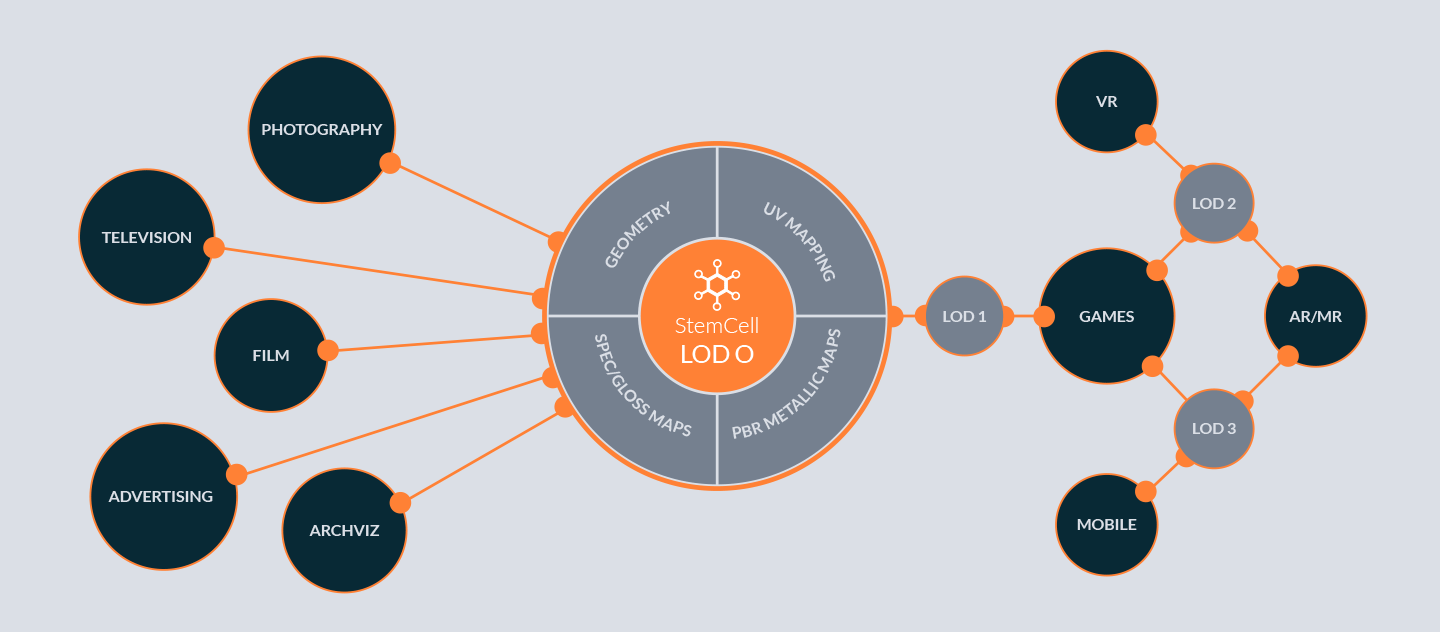
Think of LOD 0 (Level Of Detail) as the ultimate starting point for a model. Enough detail to be used in a feature film and not so much detail that it could never get it into a game. This means that In most cases an ideal StemCell model would be considered medium density since it usually contains holding edges for subdivision and would rely on normal maps for small details such as screws and bolts. The scale of the model would also be considered since larger objects may require far less intricate detail than smaller objects.
Object Scale
A jetliner exterior compared to a tricycle… which requires more detail? It’s an interesting question since it’s easy to assume that the jetliner would. But in actuality, the tricycle could end up being higher in poly count. The reason for this is quite simple: the assumed purpose of the tricycle would place the user much closer to it, meaning that smaller details may need to be modeled in, whereas the jetliner could easily get away with normal map details.
This is an important consideration to make when building your model. Don’t get lost in the minuet details. Choose an intended LOD at the very beginning and stick to it. Pull your camera back every once in awhile and look at the entire model.
 The 747 when viewed as a whole is smooth and fine details are so small there is no need model them. The Rolleiflex camera has a more complex shape with more details visible which requires more geometry to be modeled.
Minimal Mesh Density
Once you’ve determined the level of detail your building for and how the model will be used, mesh density should be a constant consideration. Always think of the model as a whole. Be aware of concentrating too much to one single area. Be cautious of too many edge loops. Edge loops only need to be present in order to maintain the primary shape of the model as well as the holding edges (subD) of a model. In the end, the mesh should feel equally balanced as you move around the object.
 Base geometry has only necessary edges for silhouette and holding edges. After smoothing geometry still appears light in tight areas with holding edges.
Unnecessary Details
One common mistake many artists make when dealing with mesh density is modeling tiny details into small objects that are barely visible when viewing the model in its entirety. In many cases, fine or small details can be represented in texture maps rather than modeled.
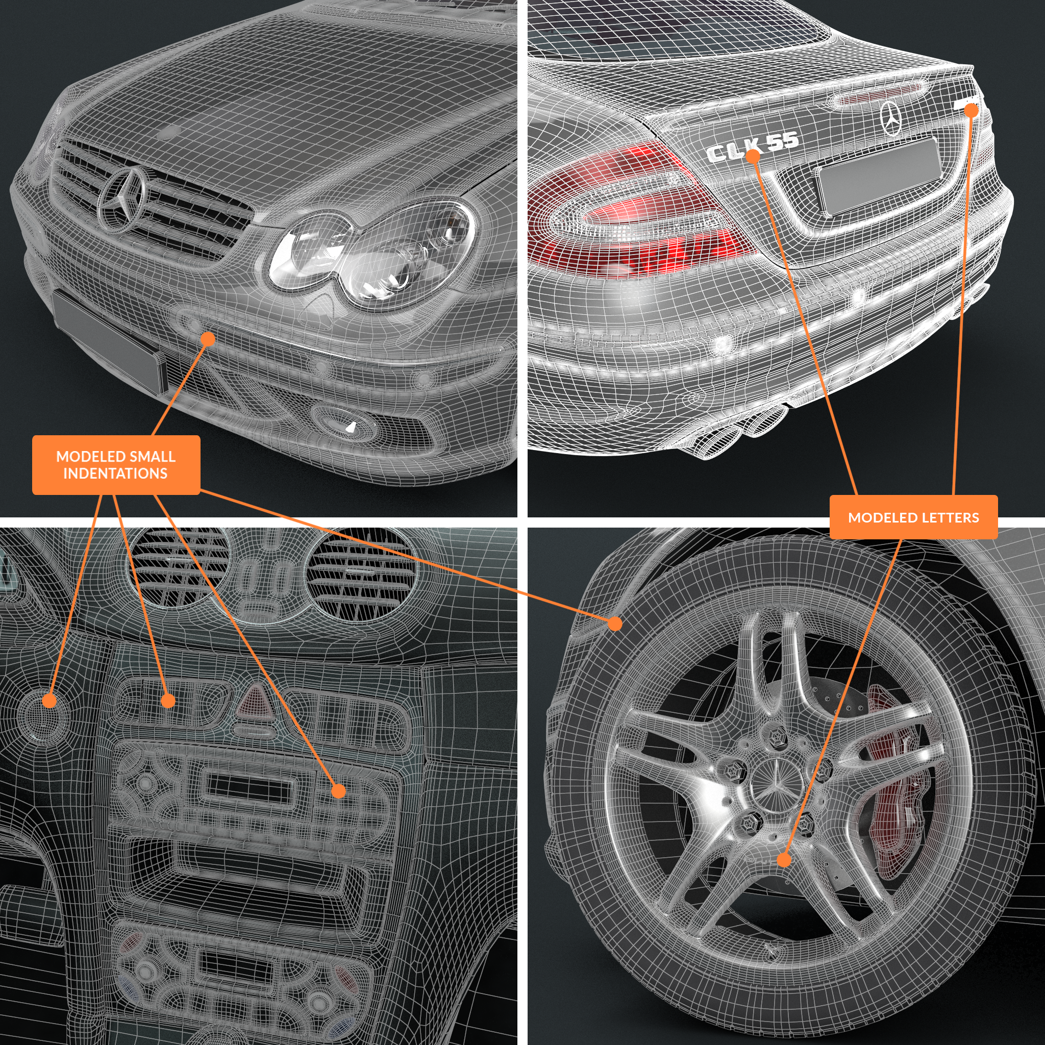 Collapsed smoothing adds to this extremely dense mesh that has small grooves, indentations, and tiny details modeled. Most of these details could be achieved with texture maps for the same amount of visible detail in the render saving thousands of polygons.
Faceting & Silhouette
Denser geometry is naturally needed for round surfaces and tight (subD) corners. With that said, round surfaces do not need to be perfectly smooth. This would make your mesh very dense. Ideally, there are just enough edges to minimize faceting so it is not as noticeable at the intended LOD. Also, flat sections of geometry do not usually need many edge loops across the surface. This adds to the final polygon count without being necessary for the intended appearance of the model.
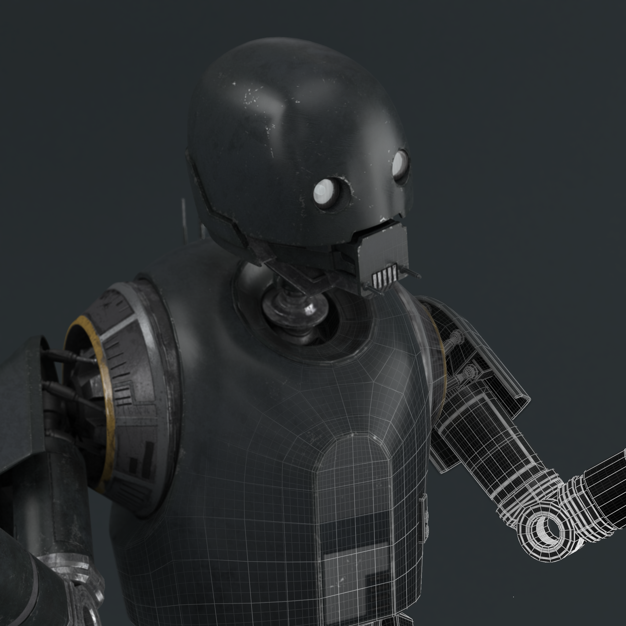
 An ideal StemCell file is clean and simple geometry. The geometry is not so dense the wireframe looks noisy, or so low it has noteable faceting when viewing the whole model.
Keeping Things Clean: A Clean Mesh Has So Many More Uses
Now let’s get a bit more technical. A good quality mesh is able to support multiple subdivisions, and with proper edge flow, allow for clean component selection and decimation. Of course perfect geometry is not a requirement of StemCell, but it certainly helps if a model is made well.
Quads
Ideally, a clean mesh should mostly consist of quads. Quads are essential for proper edge flow and ease of editability by the final user. They make it easier to add and remove edge loops with simple additive selections. Most 3D applications rely on quad based geometry for their selection tools. Triangles interrupt selection methods when attempting to edit the geometry. For this reason, Ngons (faces with more than 4 sides) are highly discouraged.
 This model consists of all quad geometry which is clean, organized, and flows well for editability.
Edge Flow
Think of edge Flow as the way selected edge loops or edge rings wrap around the model. Ideally the selection should wrap around the model in an expected way, following the edge loops or rings. Edge selection modes work by following edges of quad faces. Triangles and sometimes 5 sided poles terminate edge flow when encountered. Edge flow also changes direction at 5 sided pole. For this reason, it’s important to be mindful of edge flow and how it effects editing and selection of your model.
 Edge selecting by Ring method and Loop method wrap as expected. Depending on which side of a pole is encountered the selection may end or continue wrapping beyond the intended goal.
Holding Edges (SubD)
Holding edges are important to maintain mesh fidelity when subdividing. Without these edges smoothing modifiers can cause meshes to collapse or round out where there should be hard edges or sharp corners.
 Holding edge loops are present on all hard edges to preserve sharp, clean corners and bends after smoothing.
Scanned Meshes
Scanned meshes are allowed for StemCell, but we ask that you be mindful of both mesh density and excessive triangulation. Another common issue is scrambled UV mapping which can be undesirable to customers.
 This scanned bread loaf has sharp, rough edges that need to be clean up. The mesh is extremely dense and heavily triangulated, as normally seen in raw scan data.
If you plan on submitting scanned meshes for StemCell, we encourage you to make the extra effort of cleaning the raw mesh and ideally baking to an optimized UV map.
 This bread loaf is a scanned mesh after being retopologized. The mesh has been converted to quads with reduced density.
Special Consideration to Make For Game Engines
Since game engines are an intended target for StemCell content, there are certain considerations to make that you may not have had to deal with before. One of these considerations is the concept of water-tight modeling.
Sealed Models
Sealed Models is geometry that is sealed or leak-proof for lighting. There should be no visible backfaces through holes or gaps in an object’s geometry. This is essential for accurate lighting and rendering in game engines. Some engines, like Unity, cull backfaces by default so they do not render. Also, lighting calculations can sometime ignore backfaces, causing light or shadows to appear in unexpected places.
 These lug nut objects are identical except for the bottom. The first two have visible back faces. With backface culling on, these faces are not visible. The third has no visible backfaces so it is sealed water tight.
This does not mean all details must be from one mono-formed mesh or that all objects have to be capped. Objects intersecting the surfaces of other objects can seal geometry as long as there are no gaps or visible backfaces. This is a common practice that is more efficient than modeling a single mesh with all details extruded. Less holding edges are required when modeling this way which can significantly decreases overall polygon count. Additional benefits of modeling this way is that objects can be easily edited, removed, or smoothed separately allowing far more optimization. Intersected objects do no need cap faces that would be contained within the geometry. Deleting these faces can save significantly on poly count to put more detail into other places.
 Geometry can be intersected to seal gaps so there are no visible backfaces. This is common practice for small objects protruding from a surface like bolts, switches, buttons, etc.
Any back face that could be visible at render must be sealed. The model itself may have sealed geometry but transparent materials could make backfaces visible after rendering. If you are using Refraction or Opacity, be mindful of what can be seen through the material.
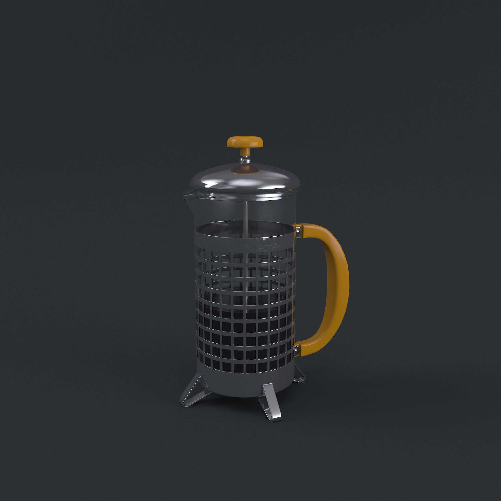 On models with transparency, there must be no visible backfaces through materials when rendered.