StemCell Transparency & Opacity
Transparent Materials
Transparent materials allow us to see through solid objects by editing visibility. By setting unique attributes for either Refraction and Opacity, we are able to achieve different effects.
Types of Transparency
There are two types of Transparency. First, there is Refraction. Refraction maps are used for objects which would distort and displace light as it passes through it. Examples of this would be such things as glass, water, and transparent plastic.
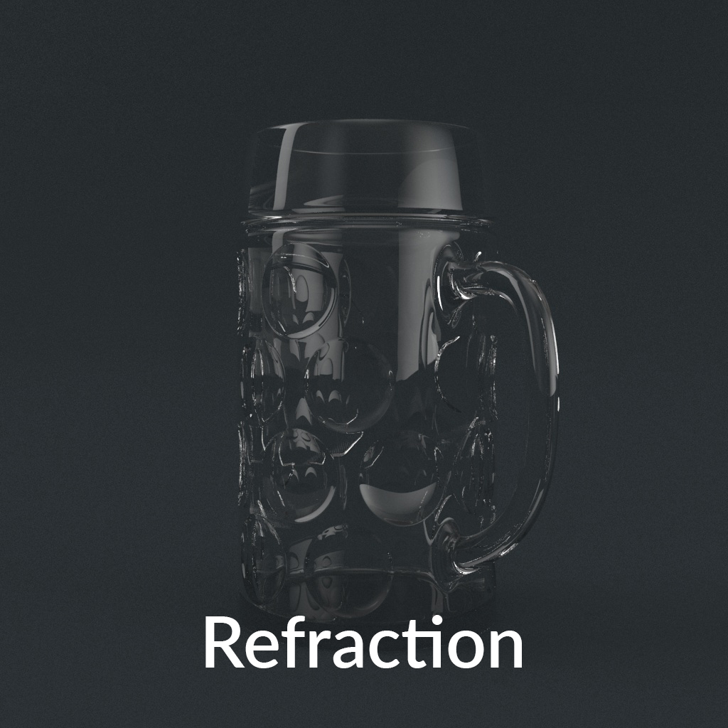 Glass objects like this beer mug model uses Refraction.
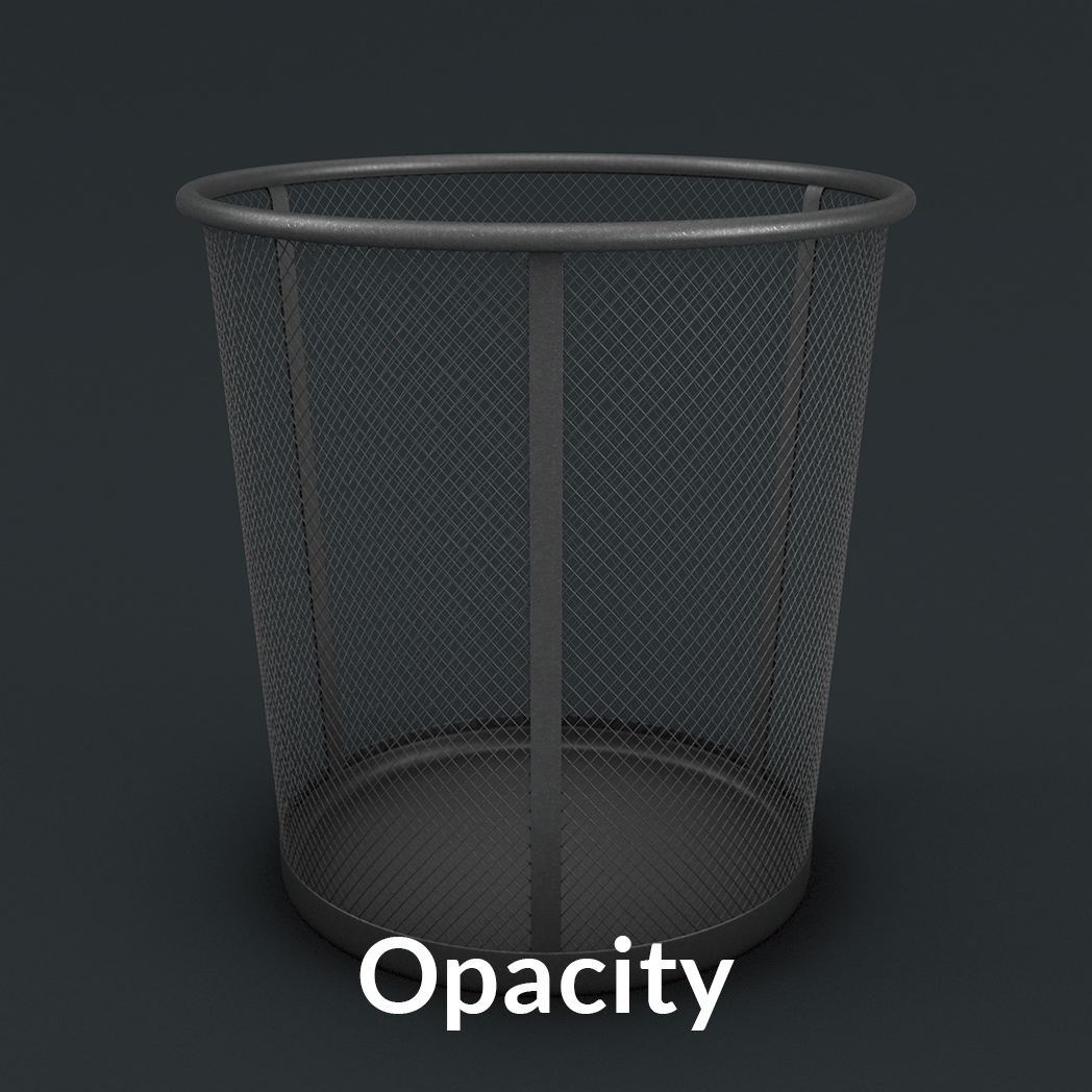 Objects like this wastebasket use opacity maps to cut out holes in the mesh.
Limitations of Processing
Because StemCell assets are driven directly from a very specific set of texture maps, there are certain limitations when it comes to the processing of materials with Transparency. To keep the quality between each DCC application and each game engine as close as possible, there are certain bits of functionality and texture maps that cannot be used for StemCell.
Exit color is used in DCC applications to show color in areas where rays of light can no longer refract any further. Setting an Exit color value or using an Exit color map is not allowed because game engines do not currently contain this input.
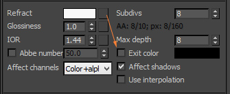 Example of Exit Color setting, shown in 3ds Max.
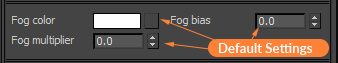 Example of Fog settings, shown in 3ds Max.
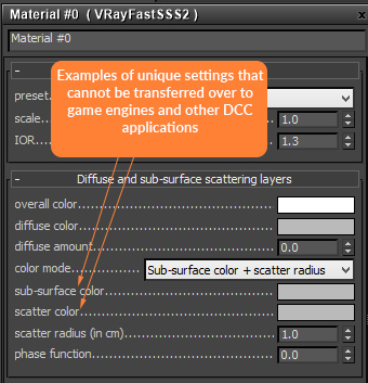 Example of Subsurface Scattering settings, shown in 3ds Max.
When creating geometry for a 3d asset that contains glass, it is important to remember that for the glass to refract properly, the geometry must have thickness.
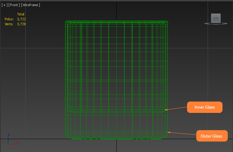 Glass model is sealed with inner and outer walls for thickness.
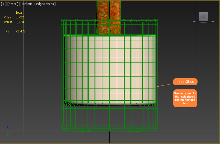 Intersecting geometry can cause rendering artifacts if not careful.
Workflow
This section is meant to help with the creation of Transparent materials using 3ds Max: V-Ray. It’s important to have consistent workflow. When creating the material you should already know what kind of transparency needs to be used. Depending on whether you are using opacity or refraction, some of your material settings will differ.
All transparent materials need to be separate objects on the model. This makes material application, object selection, render passes, and many other things easier. It is also necessary for material conversion.
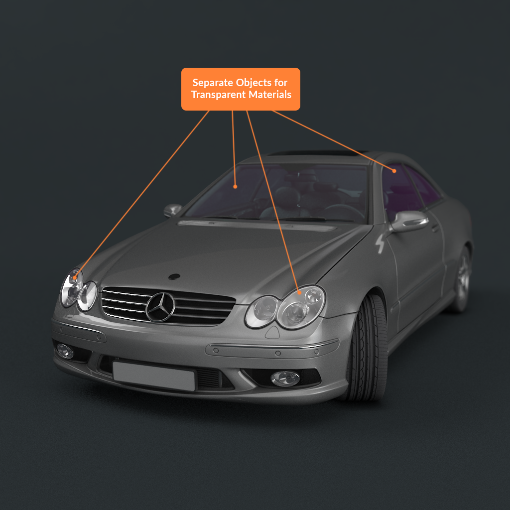 All glass on this Mercedes model are separate objects with separate transparent materials applied.
When setting values for transparency, make sure to keep the RGB value range between 2%-98%. This is roughly around RGB (5,5,5) to RGB (250,250,250).
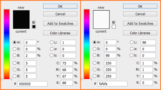 Value range should be between RGB value 5-250 range.
Index of Refraction must be set to a realistic value. Lists for reference can easily be found on the internet. Typically an average IOR value for refractive materials will range between 1.2 to 1.8. Some materials may exceed a value of 2, such as diamond.
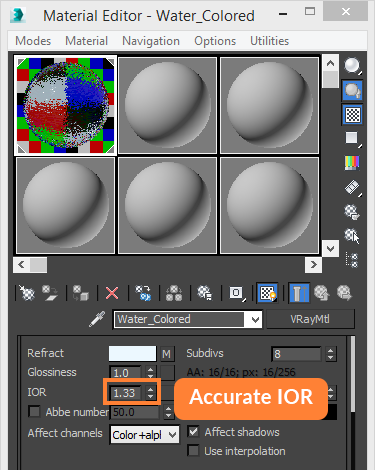 This water material has a physically accurate IOR for refraction.
Refractive materials need to be set to affect the alpha channel. These materials also need to affect shadows. Both of these settings are to ensure accurate rendering.
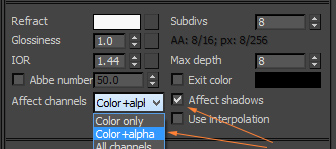 Refractive materials are set to affect alpha and affect shadows.
For Opacity maps, darker the value, more transparent. Brighter the value, more opaque.
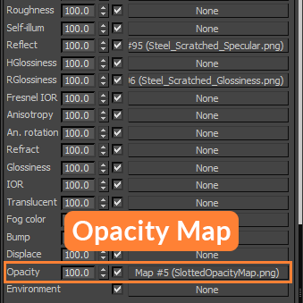
Once completed, the Opacity map will be plugged into the Opacity map slot of your materials. This map carries over into the game engines and should read correctly.
When plugging in the Opacity map, make sure it is loaded in sRGB color space for your application to prevent gamma brightening of your painted opacity values.
 Plug the opacity map to be used. Example shown in 3ds Max.
For Refraction, the darker the value the more opaque. The brighter the value the more transparent.
When creating a model that has refractive properties we allow a Refraction map to be used which is placed within the Refract Color slot of your material. You can also use the color picker to choose a value if you do not want to use a map.
When plugging in the Refraction map, make sure the map is loaded in Linear colorspace. This is to ensure that the map values painted give the same results as if you used the color picker.
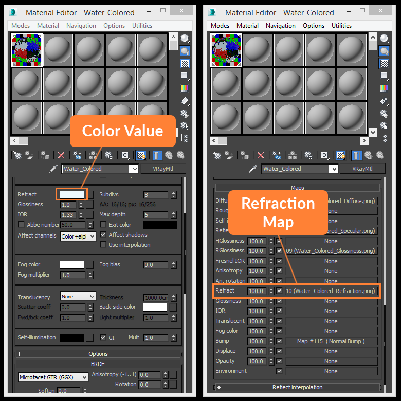 Color value or refraction map can be used. Example shown in 3ds Max.
Conversion Expectations
For DCC apps such as 3ds Max, Maya, and C4D it is common to get results that match within 90% of one another. One application may render slightly darker than another, but overall results should generally be the same.
When viewing the RT version of the StemCell model, this is when you may see some noticeable differences. Since Real time render engines need to maintain smooth frame rates, they are unable to produce the results we would normally see when viewing a model with transparency in 3ds Max. This severely limits the ability to create realistic transparent materials in game engines.
With this in mind, you will need to use your best creative judgement when creating an Opacity map for the RT asset so that it can match as closely as possible to the DCC app renders.