Clean Geometry
Clean geometry is a requirement for StemCell. It is also a good general practice that should always be done. There is often a lot of confusion as to what the definition of clean geometry is. These are the basic geometry principles that should always be kept in mind when modeling to end up with a high quality editable mesh.
Quads should make up the entire mesh unless absolutely necessary. Quads are essential for edge flow and edit-ability. They make it easy to add and remove edge loops with simple selections. Most software uses quad based geometry for their selection tools. Triangles interrupt selection methods when trying to edit geometry. Ngons (faces with more than 4 sides) are never acceptable.
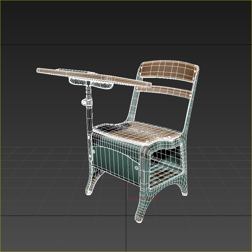
Model consists of all quad geometry which visually appears as cleanly organized and editable
Edge Flow is how selecting edge loops or rings of edges wrap the model. The selection should wrap around the model in an expected way following the edge loops. Edge selection modes work by following edges of quad faces.
Edge selecting by Ring method and Loop method wrap in expected direction following visible flow of faces.
Triangles and sometimes 5 sided poles terminate edge flow when encountered. Edge flow also changes direction at 5 sided pole. Be conscious of modeling placement for both and how it effects editing and selection on a model.
Edge selecting by Ring method and Loop method wrap as expected. Depending on which side of a pole is encountered the selection may end or continue wrapping beyond the intended.
Minimal Mesh Density is an optimization that should natural happen during modeling. Edge loops only need to be present to maintain silhouette and holding edges of a model. Mesh density applies to the model when viewing it as a whole as it would most likely be used. The most common issue with mesh density is modeling a lot of detail into small objects that are barely noticeable when looking at the whole model. Most of the time fine or small details are best represented in texture maps rather than modeling.
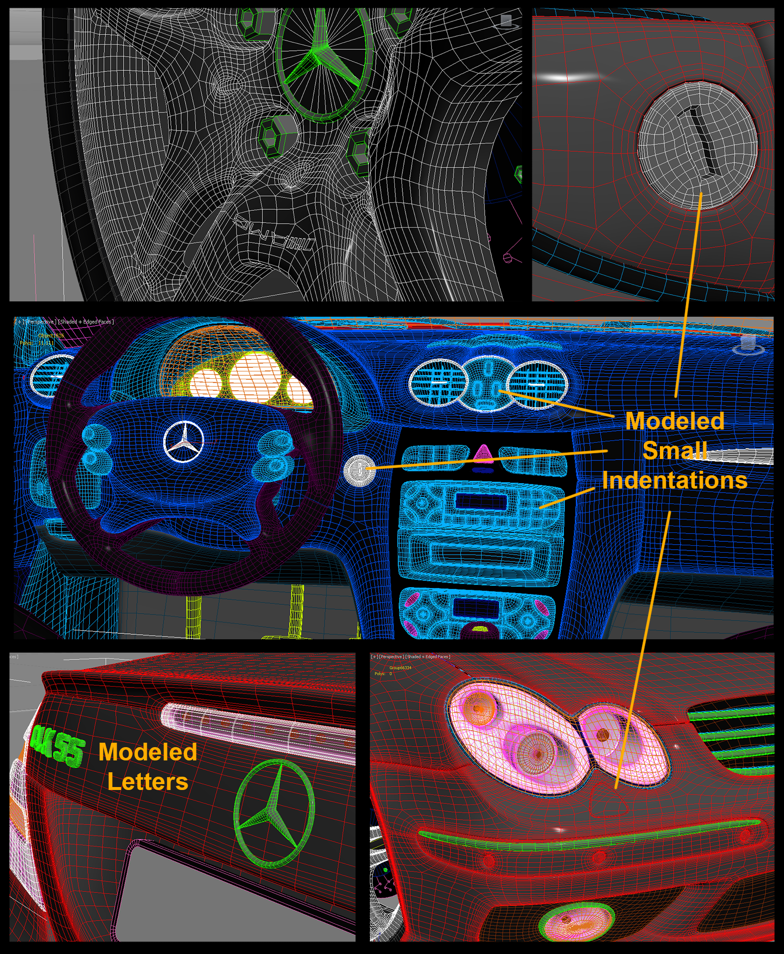
Collapsed smoothing adds to this extremely dense mesh that has small grooves, indentations, and tiny details modeled. Most of these details could be achieved with texture maps for the same amount of visible detail in the render saving thousands of polygons.
When modeling more geometry is naturally needed for round surfaces and corners which is expected. With that being said, Round surfaces do not need to be as smooth as possible. This makes meshes very dense. Ideally there is just enough edge faces to minimize faceting so it is not noticeable without starting to zoom in on the model. Flat sections of geometry do not need usually need many edge loops across the surface if any. This adds to polygon count without being necessary for detail.

An ideal StemCell file is clean and simple geometry. The geometry is not so dense the wireframe looks noisy, or so low it has noteable faceting when viewing the whole model.
Water-tight Modeling means modeling geometry that is sealed or leak proof. There should be no visible backfaces through holes or gaps in an object’s geometry. This is essential for accurate lighting and rendering purposes. Some apps, like Unity, cull backfaces by default so they do not render. Sometimes lighting calculations can also ignore backfaces causing light or shadows to appear in unexpected places.
These lug nut objects are identical except for the bottom. The first two have visible back faces. With backface culling on, these faces are not visible. The third has no visible backfaces so it is sealed water tight.
This does not mean all details must be from one mono-formed mesh or that all objects have to be capped. Objects intersecting the surfaces of other objects can seal geometry as long as there are no gaps or visible backfaces. This is a common practice that is more efficient than modeling a single mesh with all details extruded. Less holding edges are required modeling this way compared which can significantly decreases polygon count. Additional benefits of modeling this way is objects can easily be edited, removed, or smoothed separately allowing far more optimization.
Geometry can be intersected to seal gaps so there are no visible backfaces. This is common practice for small objects protruding from a surface like bolts, switches, buttons, etc.
Sealing geometry by intersecting faces can have hidden geometry inside other objects that would never be visible. Any geometry not visible from this method should be deleted so there are no unnecessary polygons.
Any geometry hidden inside objects should be deleted since it is not necessary.
Refractive Objects
When creating a model that has refractive objects like glass or liquids, those objects need to be separate objects in the model. In real-time renderers, any object with the transparent material on it is affecting by the blend mode. This is prevented by keeping solid objects separate from transparent ones. Windows on a car or glass over a gauge face are prime examples.
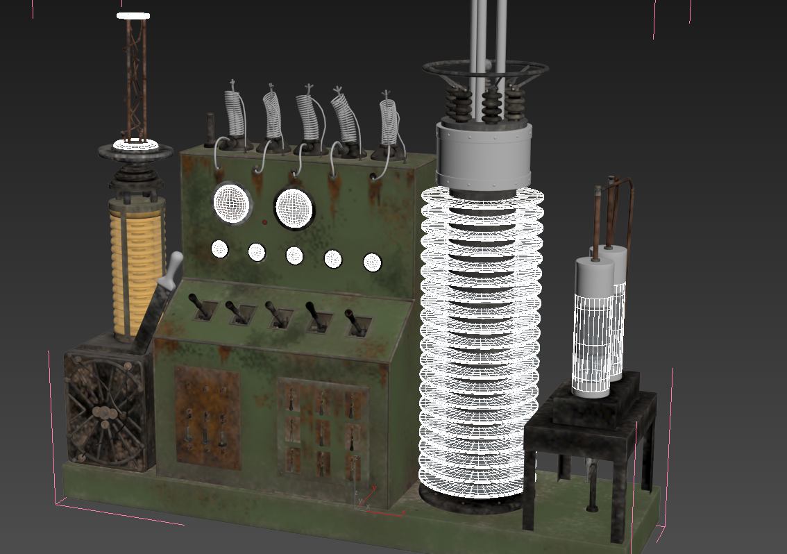
All glass objects on this model are separated making material application easier in game engines.
Glass objects should be single sided geometry of the outside surfaces only. Passing through multiple layers of transparent objects can create a variety of issues with values, lighting calculation, and reflectivity. Real-Time renders develop alpha sorting artifacts; trouble sorting which transparent faces are in front. This sorting issue can also cause reflections on outside surface to be very faint or disappear completely because the surface behind it is rendering first.
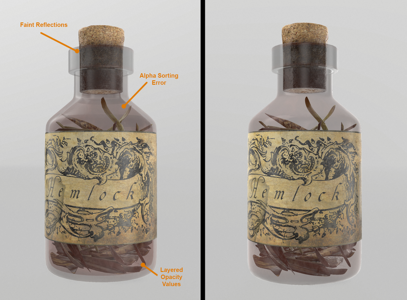
Bottle on the left has internal backfacing geometry which caused reflections to be dull, banding from alpha sorting errors, and more solid opacity from layering. Bottle on the right has only outside facing geometry. Reflections are more evenly pronounced with highlighted edges and consistent opacity. Both bottles displayed in real-time renderer.