Material Settings
When setting up materials for StemCell there are some general setting that must always be used. These settings are necessary to maximize consistency and portability to other renderers. Setting up for Mental Ray is pretty straight forward with a few minor adjustments. With Mental Ray in Maya you will be using the Mia_Material_x material. Download the Calibration scene with example materials here, or below the example image.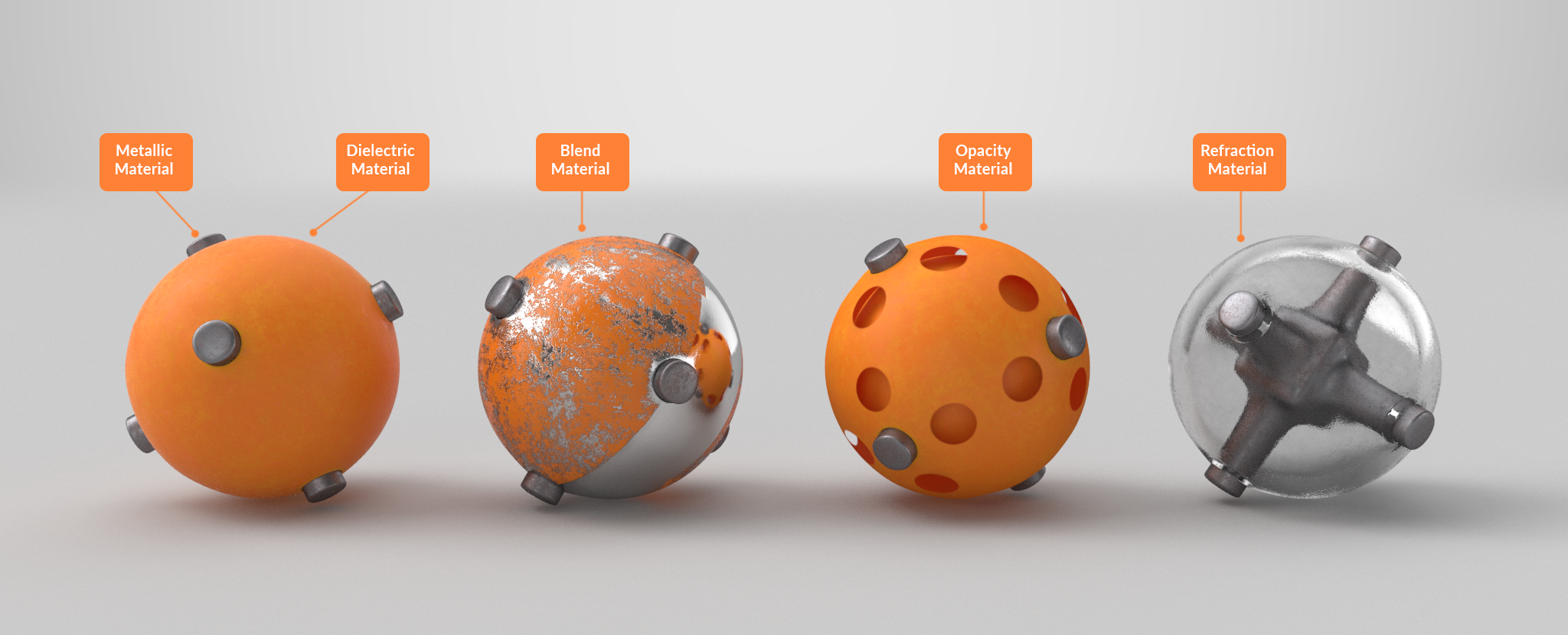 Download Material Example Calibration Scene for these five material examples.
IOR values can only be set on the Refraction Index of Refraction setting.
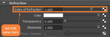 Index of Refraction value set for material.
Under the BRDF tab, make sure that “Use Fresnel Reflection” is checked on. This shading model provides the most physically accurate reflections for metallic materials.
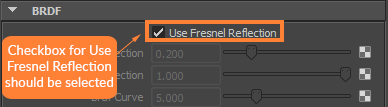 “Use Fresnel Reflection” is turned on.
Texture Map Settings
Texture maps must be applied to the right slots with the correct gamma. This section is a guide to correct material setup. You can also find the correct gamma types listed in the tables located in the Textures & Materials section of the StemCell 3D Modeling Specification.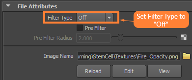 Filter Type set to “Off” on texture maps.
Plug the Diffuse map into the Diffuse Color slot. This is a sRGB map so Color Profile needs to be set to sRGB.
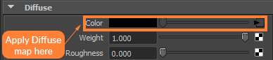 The Diffuse Color slot showing map is applied and in use.
Weight amount must always be set to 1.0 for Diffuse.
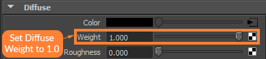 The Weight amount set to 1.0 for Diffuse.
The Specular map needs to be plugged into the Reflection Color slot. This is a sRGB map so Color Profile needs to be set to sRGB.
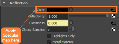 The Reflection Color slot showing map is applied and in use.
Reflectivity amount must always be set to 1.0 for Reflection.
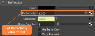 The Reflectivity amount set to 1.0 for Reflection.
If the model uses an Emissive map, this will be plugged into the Additional Color slot under the Advanced tab. This is a sRGB map so Color Profile needs to be set to sRGB.
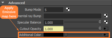 The Additional Color slot showing map is applied and in use.
All sRGB texture maps need the Color Profile set to sRGB.
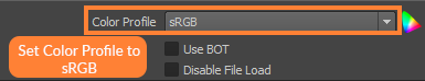 Color Profile on texture map set to sRGB.
The Glossiness texture map is going to be plugged into Reflection Glossiness, but it needs to be done in a specific way for Mental Ray to render the map like other renderers.
When loading the Glossiness texture map it needs to be assigned an sRGB Color Profile like above. Then it needs to be passed through a Color Correction node by plugging it into the Value slot. The Gamma value needs to be changed to 0.454.
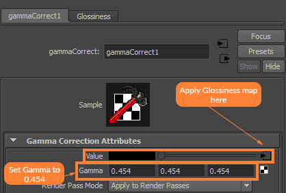 Setting the Color Correction node to .454 for Mental Ray.
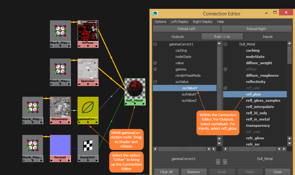
To apply the Gamma Correct node to the Reflection Glossiness slot, this will need to be done in the Hypershade. Middle mouse click the Gamma Correct node and drag it over the desired shader.
Select Other when the menu pops up, which will bring up the Connection Editor. In the Connection Editor, click the “+” next to outValue. From the expanded list, select outValueX for Outputs and refl_gloss for Inputs.
 Gamma Correction node applied to Reflection Glossiness slot.
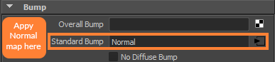 The Normal map is being applied to Standard Bump slot.
Under 2d Bump Attributes, make sure that the Normal map is set to Tangent Space Normals.
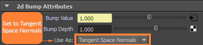 Normal map set to use Tangent Space Normals.
When plugging in a Linear map make sure that Color Profile is set to “Linear sRGB”. This applies to the Normal and Refraction Map.
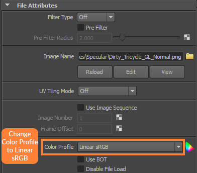 Color Profile set to “Linear sRGB”.
Transparent Materials
If transparent materials are present, they must follow the guidelines in How to setup Transparency & Opacity for StemCell.If the model uses an Opacity map, this will be plugged into the Cutout Opacity slot. This is a sRGB map so Color Profile needs to be set to sRGB.
 The Cutout Opacity slot showing map is applied and in use.
Under Color Balance, check on “Alpha is Luminance” for the Opacity Map.
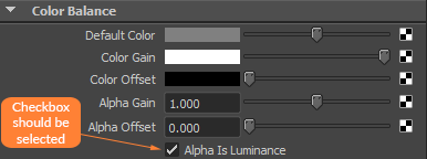 “Alpha is Luminance” is checked on for Opacity map.
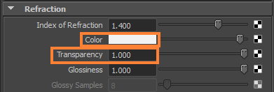
If the material uses Refraction, you may choose a value from the color picker that is Achromatic, meaning it possesses no hue information. The value used for Refraction Color should be Black, White, or a varying shade of Grey. Refraction Transparency amount must be set to 1.0 when a color value or texture map is in use.
 The Color picker used to apply Refraction.
If the material uses a Refraction map, this will be plugged into the Refraction Color slot. This map should also be Achromatic. Refraction Transparency amount must be set to 1.0 when a color or map is in use.
What if my texture map set has multiple material types?
There are some situations where a material may require a dielectric and metallic materials on the same surface. See When to use Blend Materials for more information on these situations.When an individual dielectric or metallic material can not be separated by object, that is the only time a blend material needs to be used. The Blend material is used to combine the 2 different IORs for dielectrics and metals. This way one material applied to the single object represents both surface types. A dielectric version of the material is created as Material 1 using correct low IOR value. A copy of that material is made for the metallic version as Material 2 with correct high IOR. The Metallic map is used as the Mask.
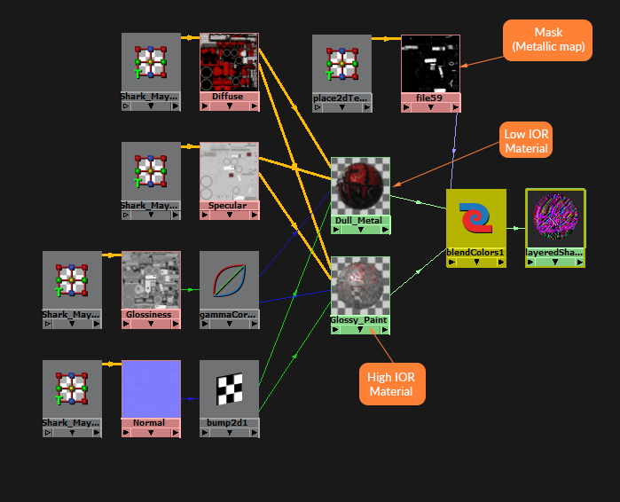 Example of a Blend Material shading network.
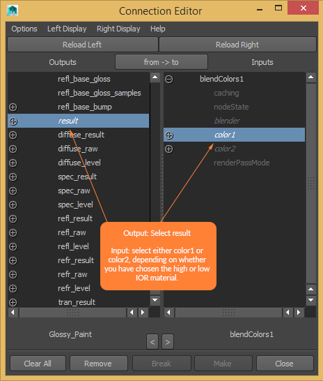
When plugging in your materials to the Blend material, typically the higher IOR material will be plugged into Color 1 while the lower IOR material will be plugged into Color 2. The two materials will then be blended together by adding the Metallic map to the Mask slot.
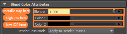 Example of a Material organization for Blend.
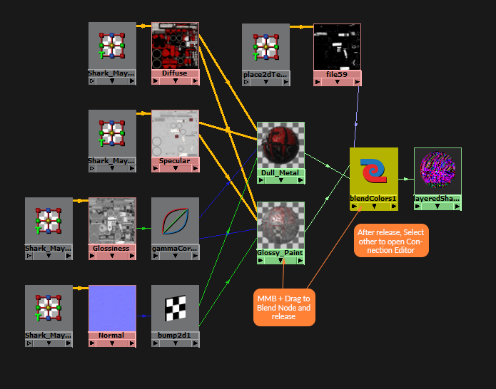
To assign the shaders to your Blend material, middle mouse click over the desired shader and drag to the Color Blend Node. Select either Color 1 or Color 2. In the Connection Editor choose “result” for the Outputs and, depending on which shader you chose, select color1 or color2 for Inputs.
 Middle mouse drag each material into the blend node to apply.
 Connection editor showing the selected material being linked to the corresponding Color.
For the Metallic map to work properly, make sure that the checkbox for Alpha is Luminance is selected.
“Alpha is Luminance” is checked on for Metallic map.
The final step is to put the Blend into a Layered Shader node. Apply the blendColor node to the Color slot of the Layered Shader by middle mouse dragging it to the slot.
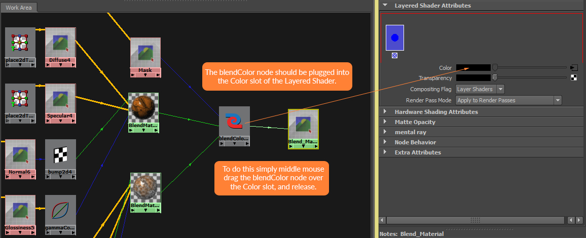 The blendColor node is applied to a Layered Shader.