

- Product Imagery Checklist
- 3D Model Product Specifications
- Generating Marmoset .mview Files
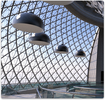
- Creating Signature Images On RGB(247,247,247) Backgrounds
- Product Names
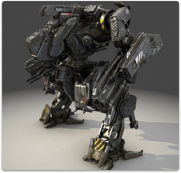
- Product Shots
- Watermarks
- Spellings of 3D Product Names
- Turntables
- Search Images
- Native File Format
- Product Descriptions
- TurboSquid Studio Scenes
- Scenes vs. Collections
- About exchange formats
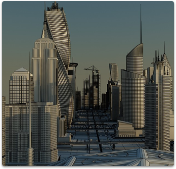
- Wireframe Images
- Polygon Count
- UV Layout Images
- Vertex Count
- Bonus Imagery
- Publishing Metadata: Geometry Type
- Unwrapped UVs Attribute
- How to Create Wireframes